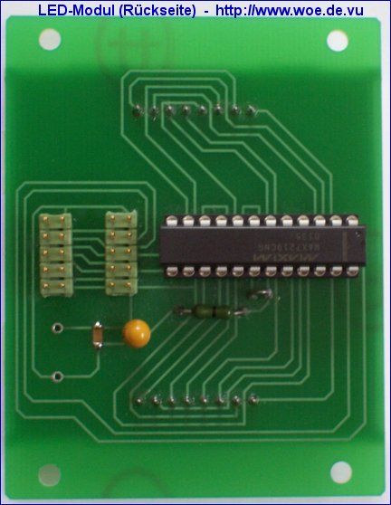
The LED moving font is built up of separate modules consisting of 64 LEDs each (8x8 matrix). The modules can be cascaced according to the desired size of the font. Each module is controlled by the LED display driver MAX7219 (or MAX7221) which can drive 64 LEDs. The display data is transferred serially to this display driver via the pins DIN, CLK and LOAD. The pin DOUT can be connected to the input DIN of the following display driver, all CLK and all LOAD pins are connected together. The datasheet is available on Maxim's homepage.
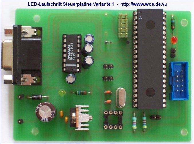
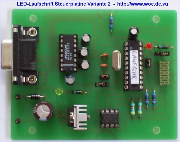
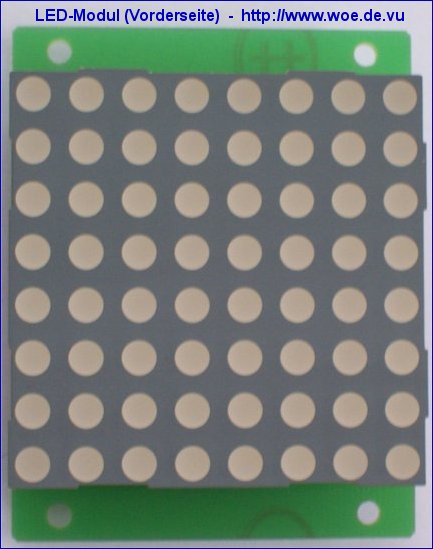
The modules are controlled by an 8051-compatible microcontroller AT89C51 (LED moving font controller variant 1) or AT89C2051 (LED moving font controller variant 2) from Atmel which provide 4 kB or 2kB flash memory on-chip. The LED display driver MAX 7219 CNG is available from Reichelt or Segor, a free sample can be ordered on the homepage of Maxim. The LED display driver is mounted together with a LED module (8x8 matrix) on the LED module PCB.
The display text is stored in a
EEPROM. The text can be downloaded via a serial RS232 connection from a PC. From the PC a text file
containing the text is sent. The baudrate can also be set to 600 Baud (via additional jumper), because some PCs
have problems with hardware handshaking, which would be necessary at 1200 or 9600 Baud download speed.
Dependent on the storage size of the EEPROM up to 2045 characters
can be stored. It is also possible to store the text in the flash ROM of the microcontroller. But
then it is necessary to reassemble the program code if the text is changed and to reprogram the
flash ROM. If an EEPROM is used, changes of the text can be done easily via serial downloading.
A maximum of 11 LED modules (each module consisting of 8x8 LEDs) can be used. The moving font
is already working with 1 module.
Adjusting moving speed: in EEPROM-Mode, 255
speed values can be set. The selected value can be transmitted via serial
interface and will be stored in a byte in EEPROM.
The schematic and the software can be downloaded here:
![]() Project files for hardware and software in ZIP format:
Project files for hardware and software in ZIP format:
LED moving font V2.3
For the hardware the freeware version of Eagle 3.55 is required. It is available for free from CadSoft.
![]() Schematic and component placement in GIF format:
Schematic and component placement in GIF format:
LED moving font controller variant 1 (for AT89C51):
Schematic of LED moving font controller variant 1
Component placement of LED moving font controller variant 1
LED moving font controller variant 2(for AT89C2051):
Schematic of LED moving font controller variant 2
Component placement of LED moving font controller variant 2
LED module:
Schematic LED module
Component placement of LED module
![]() Printed circuit board:
Printed circuit board:
There are professionally manufactured unpopulated printed circuit boards available for this project, named:
MAT_CON1.BRD (LED moving font controller variant 1 for AT89C51)
MAT_CON2.BRD (LED moving font controller variant 2 for AT89C2051)
LEDMODUL.BRD (PCB for 1 LED module TC23-11EWA)
More information is available here:
Printed circuit boards for WOE projects
![]() Programmed microcontroller:
Programmed microcontroller:
If you are interested in a programmed microcontroller, please send an
email including the project name.
![]() Did you like this project?
Did you like this project?
So feel free to support WOE with a small donation. You will support the development of further free projects on this site. Thank you.
Suitable 8x8 LED dot matrix displays for the LED moving font:
For each LED module a 8x8 LED dot matrix display is required with common cathode columns
and common anode rows. You can build the dot matrix displays with seperate LEDs on a universal PCB
or you can use 8x8 LED dot matrix panels. A suitable type is the display TC23-11EWA manufactured by Kingbright, a suitable unpopulated PCB is available, look ahead.
The color of this LED dot matrix display is red, but it is also available in different colors.
Sources of supply for 8x8 LED dot matrix displays TC23-11EWA:
8x8 LED dot matrix displays TC23-11EWA (Manufacturer: Kingbright, color: red,
technical data) are available via the distributors of
Kingbright, e.g.
menges electronic.
From Pollin Electronic there was a complete TV tuner available (Sonderliste Nr. 1/2000, page 83). The tuner is programmable via I²C-Bus and provides a FBAS signal at its output. There is also the homepage of Georg Acher containing information about this tuner. I have developed a control circuit for this tuner which uses the AT89C2051 from Atmel. Operating is done via three keys: key C/P switches between the program number and the channel number, with keys + and - you can switch up or down. The adjusted channels are stored in an EEPROM. The program or channel number is displayed on a four digit LC- or LED-Display which is controlled via I²C-Bus.
The schematic and the software can be downloaded here:
![]() Project files for hardware and software in ZIP format:
Project files for hardware and software in ZIP format:
TV-Tuner V1.0
For the hardware the freeware version of Eagle 3.55 is required. It is available for free from CadSoft.
![]() Schematics in GIF format:
Schematics in GIF format:
Schematic of TV tuner
Schematic of LCD display for TV tuner
Schematic of LED display for TV tuner
![]() Programmed microcontroller:
Programmed microcontroller:
If you are interested in a programmed microcontroller, please send an
email including the project name.
![]() Did you like this project?
Did you like this project?
So feel free to support WOE with a small donation. You will support the development of further free projects on this site. Thank you.
 The LED clock consists of 60 LEDs which are placed circular around a common analog clock. The LEDs
are used to display the seconds. Essential part of this circuit is the LED driver MAX7219 from
Maxim. A datasheet is
available on Maxim's homepage. The clock is controlled by the microcontroller AT89C2051 from
Atmel. This microcontroller
is clocked at a frequency of 12 MHz from which results a time base of 1 microsecond. Via software
dividers one clock impulse per second is generated which is used for updating the LED display.
The LED clock consists of 60 LEDs which are placed circular around a common analog clock. The LEDs
are used to display the seconds. Essential part of this circuit is the LED driver MAX7219 from
Maxim. A datasheet is
available on Maxim's homepage. The clock is controlled by the microcontroller AT89C2051 from
Atmel. This microcontroller
is clocked at a frequency of 12 MHz from which results a time base of 1 microsecond. Via software
dividers one clock impulse per second is generated which is used for updating the LED display.
Two different display modes can be adjusted by a jumper:
1. The LEDs are switched on one by one every second until all LEDs are on after one minute.
After that they are switched off one by one every second. This sequence is repeated.
2. The LEDs are switched on one by one every second until all LEDs are on after one minute.
After that it starts from the beginning by switching on the first LED.
The schematic and the software can be downloaded here:
![]() Project files for hardware and software in ZIP format:
Project files for hardware and software in ZIP format:
LED clock V1.0
For the hardware the freeware version of Eagle 3.55 is required. It is available for free from CadSoft.
![]() Schematic in GIF format:
Schematic in GIF format:
Schematic of LED clock
![]() Programmed microcontroller:
Programmed microcontroller:
If you are interested in a programmed microcontroller, please send an
email including the project name.
![]() Did you like this project?
Did you like this project?
So feel free to support WOE with a small donation. You will support the development of further free projects on this site. Thank you.
Serial data which is transmitted via a RS232 interface is converted to I²C-Bus format. The I²C-Bus is provided from a microcontroller AT89C2051 via software. So it's possible to control I²C-Bus circuits from a PC with low expense. The PC acts as the I²C-Bus master (indirectly via the microcontroller). I²C data can be both written and read, I²C acknowledge bits can be both set and evaluated.

The schematic and the software can be downloaded here:
![]() Project files for hardware and software in ZIP format:
Project files for hardware and software in ZIP format:
Serial-I²C-Converter V1.1
For the hardware the freeware version of Eagle 3.55 is required. It is available for free from CadSoft.
![]() Schematic and component placement in GIF format:
Schematic and component placement in GIF format:
Schematic of Serial-I²C-Converter
Component placement of Serial-I²C-Converter
![]() Printed circuit board:
Printed circuit board:
There is a professionally manufactured unpopulated printed circuit board available for this project, named SER_I2C.BRD
More information is available here:
Printed circuit boards for WOE projects
![]() Programmed microcontroller:
Programmed microcontroller:
If you are interested in a programmed microcontroller, please send an
email including the project name.
![]() Did you like this project?
Did you like this project?
So feel free to support WOE with a small donation. You will support the development of further free projects on this site. Thank you.
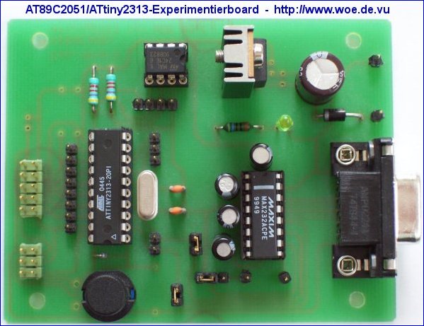
The AT89C2051/ATtiny2313 evaluation board is suited well for building and testing microcontroller circuits. You can either use an AT89C2051 or an ATtiny2313, both microcontrollers are almost pincompatible, just the reset pin has different polarity. The ATtiny2313 has the advantage that it can be programmed in-circuit via SPI. Furthermore it supports On-Chip-Debugging via the built-in DebugWire interface. Debugging can be done via the reset pin with the "JTAGICE mkII" from Atmel.
The port pins are connected to terminals. A serial RS232 interface is already implemented on board which can also be disabled in order to get further port pins. A serial I²C-EEPROM can be used as a nonvolatile memory for configuration data. Via I²C-Bus other peripheral components can be connected to the evaluation board. A stabilized 5V supply is also implemented on board.
The schematic and the layout of the board can be downloaded here:
![]() Project files for hardware and software in ZIP format:
Project files for hardware and software in ZIP format:
AT89C2051/ATtiny2313 evaluation board V1.1
For the hardware the freeware version of Eagle 3.55 is required. It is available for free from CadSoft.
![]() Schematic and component placement in GIF format:
Schematic and component placement in GIF format:
Schematic of AT89C2051/ATtiny2313 evaluation board
Component placement of AT89C2051/ATtiny2313 evaluation board
Attention: Please consider the different component placement options according to the selected microcontroller!
![]() Printed circuit board:
Printed circuit board:
There is a professionally manufactured unpopulated printed circuit board available for this project, named AT89_EXP.BRD
More information is available here:
Printed circuit boards for WOE projects
![]() Programmed microcontroller:
Programmed microcontroller:
If you are interested in a programmed microcontroller, please send an
email including the project name.
![]() Did you like this project?
Did you like this project?
So feel free to support WOE with a small donation. You will support the development of further free projects on this site. Thank you.
Using this programmer you can program the internal flash of the microcontroller AT89C2051 from Atmel. The AT89C2051 programmer is connected via the serial RS232 interface to a PC. In comparison with other programmers, you do not need a special software, a terminal program is sufficient. So there are no platform dependent limitations and it can be used universally.
Generally the programmer supports two different modes:
1. User mode: The desired operation Program (including Erase),
Verify, Read or Lockbits can be selected via a BCD switch and started by pressing a button. The desired
programming data will be transmitted or received in binary format via the RS232 interface.
A special software data handshake is not required. A LED shows the current status.
2. Remote mode: In remote mode, the BCD switch and the button are not required,
because the operations are selected via special remote commands from RS232 interface, followed by the binary data like in
user mode. When the operation is finished, a status code is transmitted back, so it would also be possible to control
the programmer with an own developed software.

The schematic and the software can be downloaded here:
![]() Project files for hardware and software in ZIP format:
Project files for hardware and software in ZIP format:
AT89C2051 programmer V1.1
For the hardware the freeware version of Eagle 3.55 is required. It is available for free from CadSoft.
![]() Schematic and component placement in GIF format:
Schematic and component placement in GIF format:
Schematic of AT89C2051 programmer
Component placement of AT89C2051 programmer
![]() Printed circuit board:
Printed circuit board:
There is a professionally manufactured unpopulated printed circuit board available for this project, named PRG2051.BRD
More information is available here:
Printed circuit boards for WOE projects
![]() Programmed microcontroller:
Programmed microcontroller:
If you are interested in a programmed microcontroller, please send an
email including the project name.
![]() Did you like this project?
Did you like this project?
So feel free to support WOE with a small donation. You will support the development of further free projects on this site. Thank you.
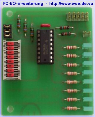
The I²C-I/O-Expander is an example for easily providing input and output ports for the I²C bus.
The I²C circuit PCF8574 provides 8 bidirectional port pins. A LED (LD1-LD8) is connected to each port pin,
which is activated with a LOW signal at the corresponding port pin.
Furthermore a DIP switch (S1-1 - S1-8) is connected to each ort pin. At opened switch, the PCF8574 reads a HIGH signal,
at closed switch it reads a LOW signal, but therefore it is necessary to set the corresponding port pins of the PCF8574
to a HIGH signal via I²C bus. The position of the switch is also shown via a LED,
it is activated at closed switch.
A
datasheet of the PCF8574 is available from Philips.
The assembler code I2C_IO.ASM included in the ZIP file shows a demo program for an
AT89C2051 microcontroller. The I²C bus is realized via software:
P3.7 = SDA, P3.5 = SCL. You can use the schematic of the AT89C2051 evaluation board as an example.
The I²C signals SDA and SCL and the supply voltage are connected to J5 of that board.
Via DIP switch S1-8 of the I²C-I/O-Expander, you can select between two different
LED movements for the LEDs LD1-LD7:
S1-8 open: LEDs LD1 - LD7 are switched sequentially on and off
S1-8 closed: one lighting point moves between LD1 and LD7
LED LD8 shows the selected mode: it is activated at closed switch S1-8.
The schematic and the software can be downloaded here:
![]() Project files for hardware and software in ZIP format:
Project files for hardware and software in ZIP format:
I²C-I/O-Expander V1.1
For the hardware the freeware version of Eagle 3.55 is required. It is available for free from CadSoft.
![]() Schematic and component placement in GIF format:
Schematic and component placement in GIF format:
Schematic of I²C-I/O-Expander
Component placement of I²C-I/O-Expander
![]() Printed circuit board:
Printed circuit board:
There is a professionally manufactured unpopulated printed circuit board available for this project, named I2C_IO.BRD
More information is available here:
Printed circuit boards for WOE projects
![]() Programmed microcontroller:
Programmed microcontroller:
If you are interested in a programmed microcontroller, please send an
email including the project name.
![]() Did you like this project?
Did you like this project?
So feel free to support WOE with a small donation. You will support the development of further free projects on this site. Thank you.
The AVR JTAG Emu is a low-cost JTAG debugger for the microcontrollers of the ATmega series, that support onchip-debugging via JTAG interface, for example the microcontrollers ATmega16, ATmega162, ATmega32, ATmega128. The AVR JTAG Emu is connected via the serial RS232 interface to a PC, debugging can be done via the free software AVR-Studio from Atmel. The AVR JTAG Emu first has to be programmed with a suitable bootloader (e.g. Evertool), after that the current firmware can be transferred via AVR-Studio. Boot-Jumper JP1 has to be closed for that.
The schematic and the software can be downloaded here:
![]() Project files for hardware and software in ZIP format:
Project files for hardware and software in ZIP format:
AVR JTAG Emu V1.1
For the hardware the freeware version of Eagle 3.55 is required. It is available for free from CadSoft.
![]() Schematic and component placement in GIF format:
Schematic and component placement in GIF format:
Schematic of AVR JTAG Emu
Component placement of AVR JTAG Emu
![]() Printed circuit board:
Printed circuit board:
There is a professionally manufactured unpopulated printed circuit board available for this project, named AJEMU.BRD
More information is available here:
Printed circuit boards for WOE projects
![]() Programmed microcontroller:
Programmed microcontroller:
If you are interested in a programmed microcontroller, please send an
email including the project name.
![]() Did you like this project?
Did you like this project?
So feel free to support WOE with a small donation. You will support the development of further free projects on this site. Thank you.
Information and projects for displays can be found on own sites divided into LED, LCD and VFD. Some projects on these sites: serially controlled LED display, serially controlled LC-display ...
![]() Information around LC-Displays
Information around LC-Displays
![]() Information around Vacuum-Fluorescent-Displays (VFD)
Information around Vacuum-Fluorescent-Displays (VFD)
Some internet locations where datasheets can be searched for are listed on the site Datasheet search.
The free newsletter of World Of Electronics (in German language) can be subscribed to on this site.
This site will be continuously expanded.
© 1999-2007 ![]()